Harvard Undergraduate Robotics Club
{Winner of the Robotics Design Award and 2nd Place Finisher at Brown University’s 2017 IEEE Robotics Competition}
Challenge
To build and design a small, self-contained robot to navigate a maze, traveling from a specified corner to the center in the shortest time possible.
Engineering Stuart, the Robotic Micromouse

Technical Specifications
Improvements made to the 2016 Micromouse Robot
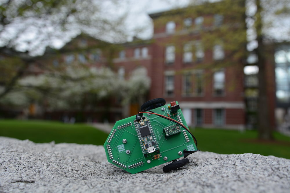
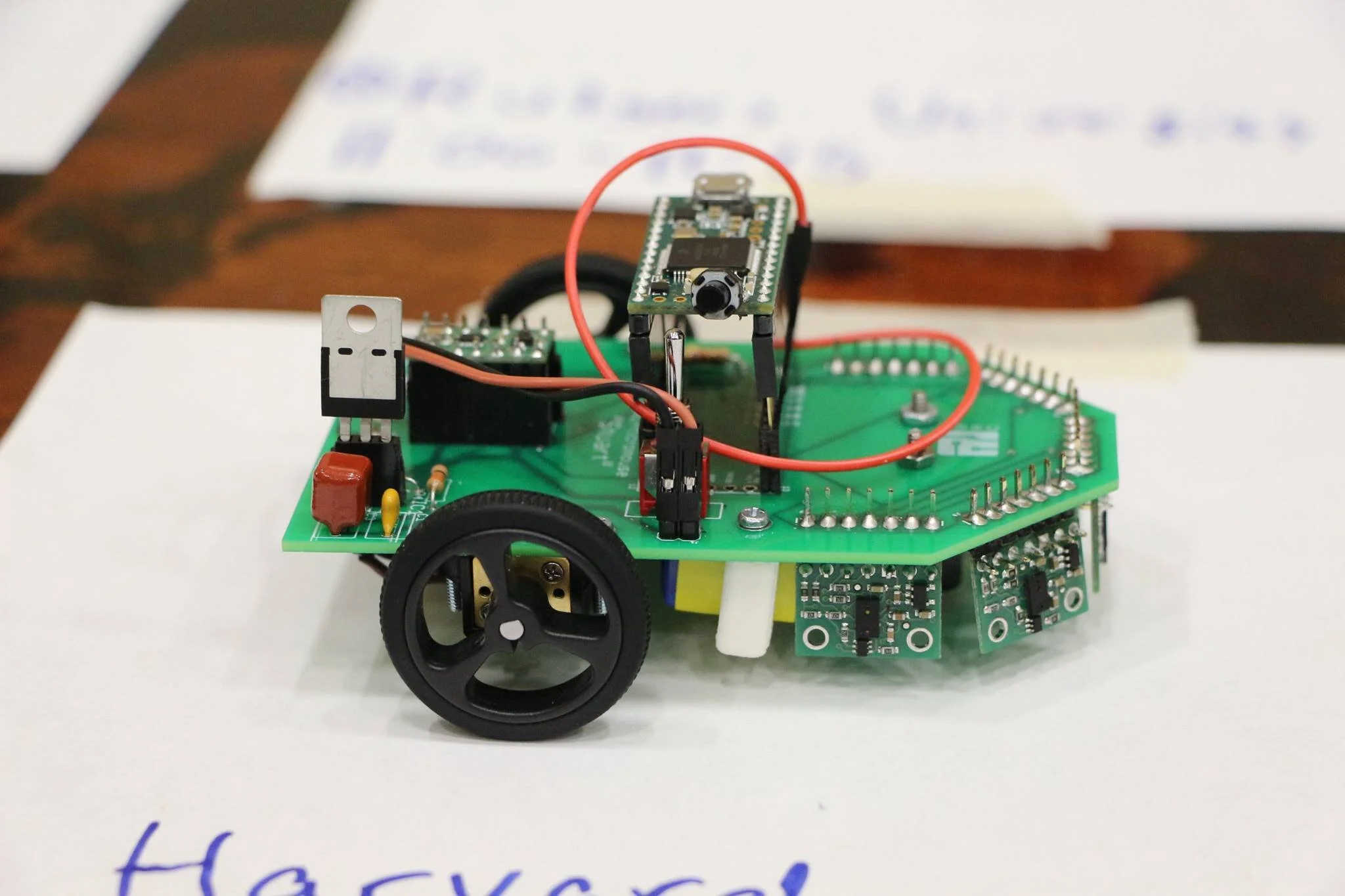
Lowered robot’s center of gravity to maximize stability.
Improved aerodynamics and acceleration time by moving battery closer to the ground.
Maximized distance to wall detection by increasing sensor supply.

Product Development
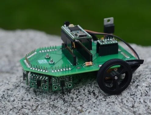
Team discussion led to the design of an integrated electronic system dedicated to improving the robot’s mechanical performance in competition. Autodesk EAGLE was used by both electrical and mechanical sub-teams, collaboratively, in modelling the printed circuit board (sent to Advanced Circuits for manufacturing). Five sensors were attached below the PCB’s front, pointed orthogonal to the ground to calculate the distance between the robot and wall. This modification reduced the robot’s overall weight and manufacturing costs.


Chemically Driven Robotic Vehicle
Chem-E-Car Team Founder, Project Manager
Challenge
To design and construct a car that is powdered with a chemical energy source that will carry a specified load over a given distance and stop.
Engineering the Chem-E-Car
Mechanical/Electrical/Chemical Assembly

Chassis Design
Technical specifications, as provided by AIChE’s Chem-E-Car Competition Guidelines, we ensured to integrate onto the chassis were to:
Brake via a chemical reaction stopping mechanism.
Be an autonomous vehicle.
Have fuel that had to be synthesized by students.
Carry a container with up to 500 mL of water without spilling.
Have dimensions: 30 cm x 20 cm x 40 cm.

Product Development
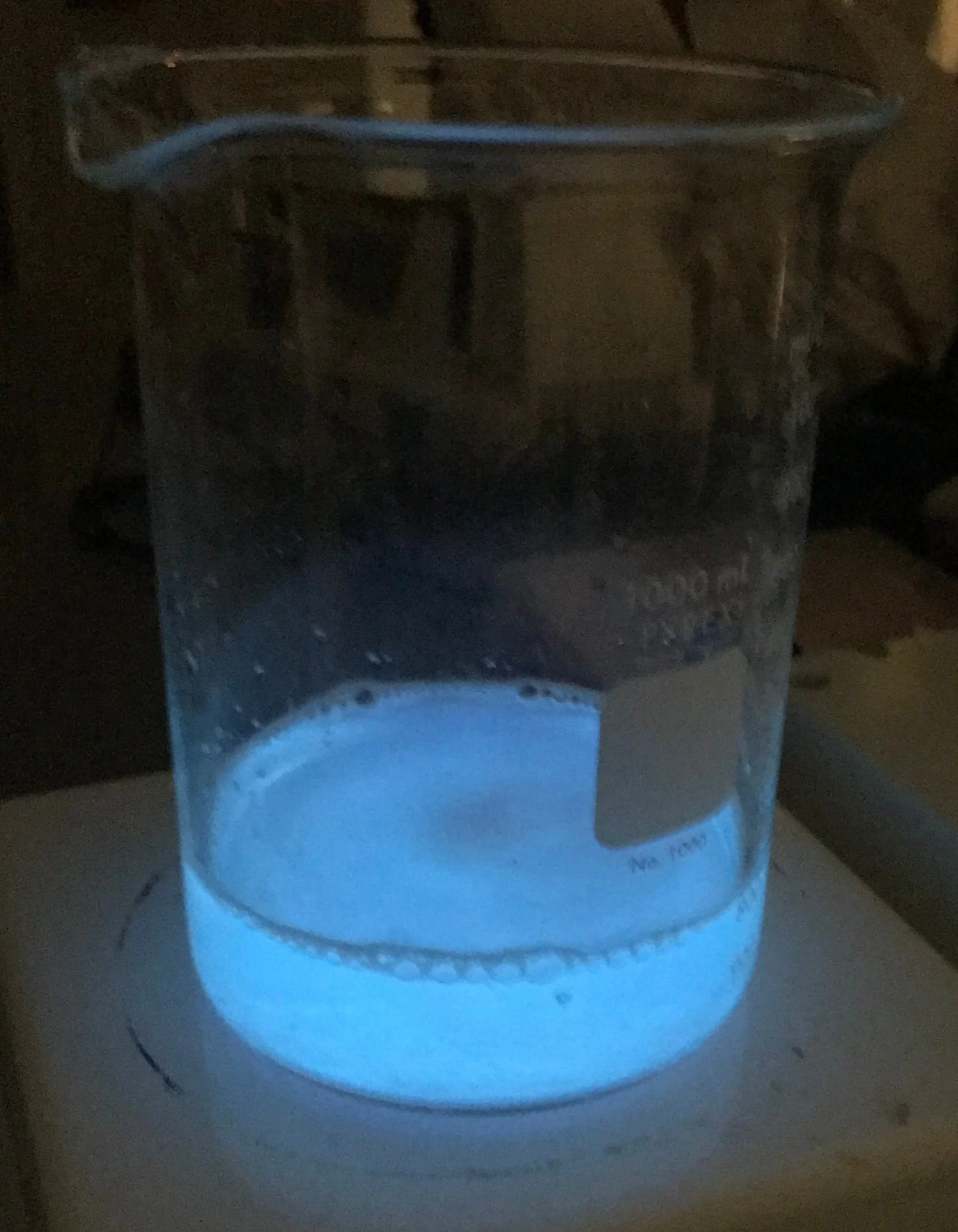
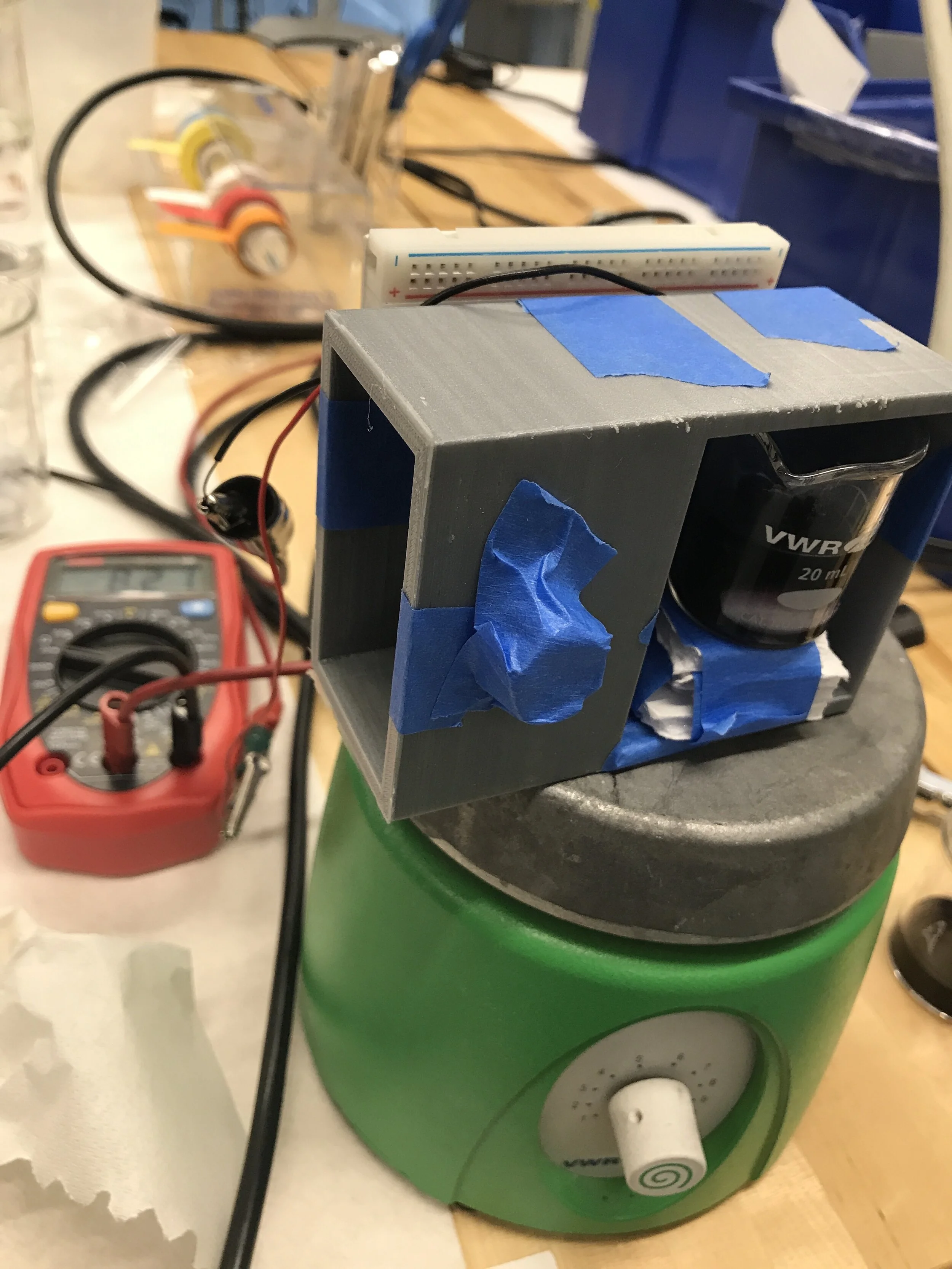
A photo resistor is able to capture luminosity change occurring in an oscillating clock reaction (as shown below), which is intended to gradually stop the dc motors connected to the front wheels. The chamber (on the right) ensures that the photo resistors are highly receptive to the reaction’s color change.
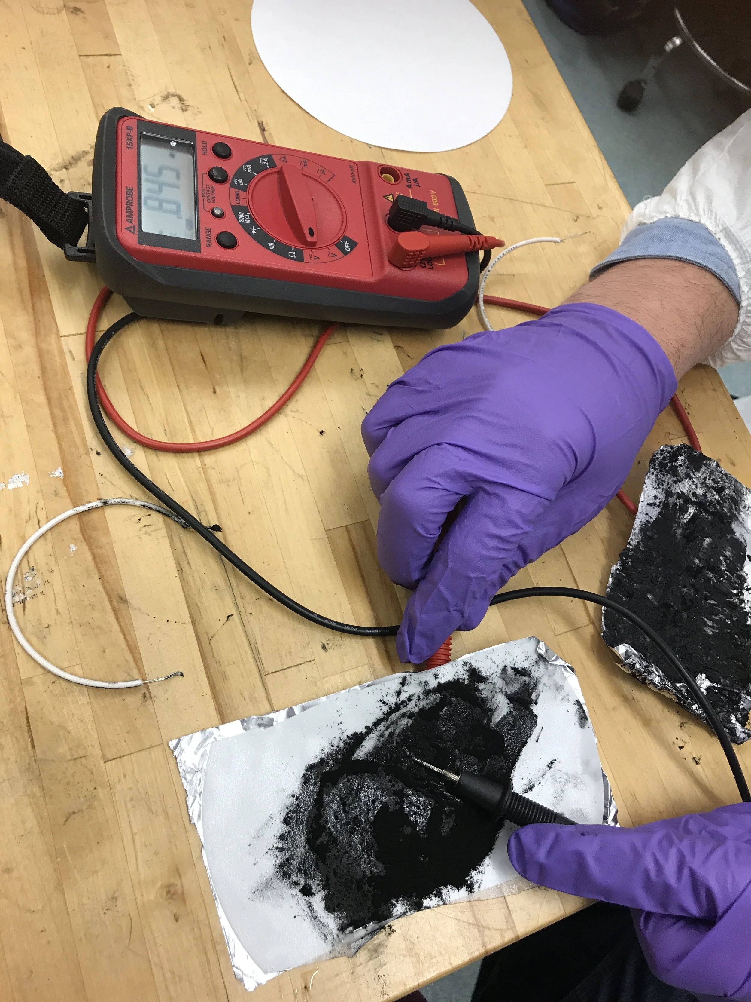
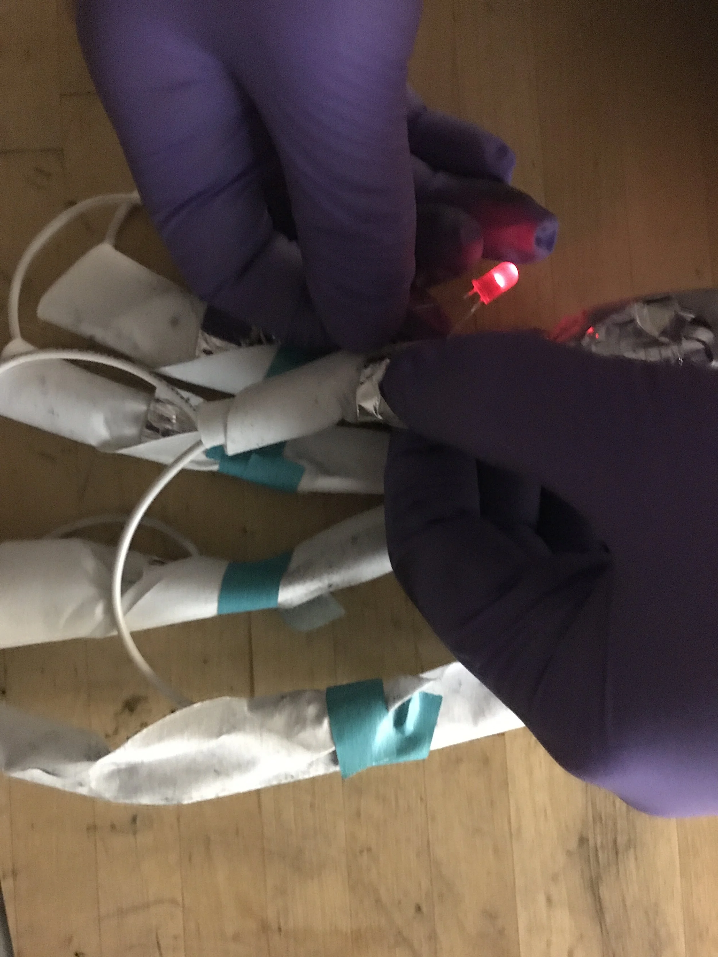
We prepared aluminum-based battery packs, which generated over 3 volts! The microcontroller is being used to relay both fuel and braking inputs into the motors, causing desired autonomous vehicular movement across the competition floor.
Testing Vehicular Braking Systems

Iodine Clock Reaction

Chemiluminscent Reaction